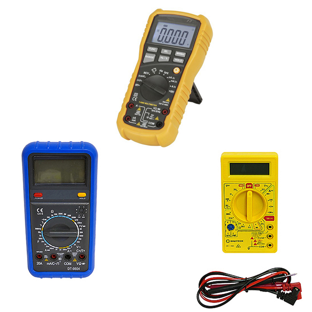
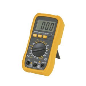
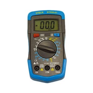
MULTIMETERS: Auto-ranging (DT832, HSG900G)
A variety of Multimeters for use in the science laboratory.
A multi-tester, commonly referred to as a VOM (volt-ohm-milliammeter), is an electronic measuring instrument that combines multiple measurement operations into a single unit. Multimeters capable of measuring voltage, current, and resistance. Analog types display readings using a microammeter with a moving pointer. Digital kinds (DMM, DVOM) include a numeric display and may additionally display a bar graph showing the measured value. They have also rendered analog multimeters obsolete because they are now less expensive, more accurate, and more physically durable. A multimeter combines a DC voltmeter, an AC voltmeter, an ammeter, and an ohmmeter. A non-amplified analog multimeter consists of a meter movement, range resistors, and switches; VTVMs, on the other hand, are amplified analog meters with active circuitry. For measuring DC voltage with an analog meter movement, a series resistor is connected between the meter movement and the circuit under test. A switch (typically rotary) permits the addition of a greater resistance in series with the meter movement in order to measure higher voltages. The product of the basic full-scale deflection current of the movement, and the sum of the series resistance and the movement’s own resistance, gives the full-scale voltage of the range.
A meter movement that required 1 mA for full-scale deflection and had an internal resistance of 500 would have 9,500 of series resistance on the 10 V range of the multimeter. For analog current ranges, parallel low-resistance shunts are connected to the meter movement to redirect the majority of the current around the coil. Again, the shunt resistance for a hypothetical 1 mA, 500 movement on a 1 A range would be just over 0.5. Instruments with moving coils can only respond to the average value of the current passing through them. To measure alternating current, which varies up and down repeatedly, a rectifier is inserted into the circuit so that each negative half cycle is inverted; the result is a variable, nonzero DC voltage whose maximum value, assuming a symmetrical waveform, is half the AC peak-to-peak voltage.
Simple rectifier-type circuits can only be calibrated for sinusoidal waveforms because the rectified average value and the root mean square (RMS) value of a waveform are identical only for square waves. Other wave forms necessitate a different calibration factor to relate RMS to the mean value. Typically, this type of circuit has a limited frequency range. Since practical rectifiers contain a voltage loss that is not zero, the accuracy and sensitivity at low AC voltage levels are inadequate. To measure resistance, switches within the instrument cause a small battery to pass a current through the device being tested and the meter coil. Since the available current is dependent on the level of charge of the battery, which varies over time, most multimeters have a zero adjustment for the ohm scale. In the typical circuits found in analog multimeters, the meter deflection is inversely proportional to the resistance, so full-scale is 0 and greater resistance corresponds to smaller deflections. The ohms scale is compressed, so lower resistance values have a higher resolution. Instruments that are amplified simplify the construction of series and shunt resistor networks. By decoupling the internal resistance of the coil from the selection of the series and shunt range resistors, the series network becomes a voltage divider. When AC measurements are necessary, the rectifier can be positioned after the amplifier stage to improve low-range precision. For resistance measurements, digital instruments, which must have amplifiers, employ the same principles as analog instruments. This avoids the scale compression present in analog meters, but necessitates a precise source of current. A digital multimeter with auto-ranging is capable of automatically adjusting the scaling network so that the measurement circuits utilize the full precision of the A/D converter.


